|
FAQ section
|
How to test Port Forwarding |
 |
 |
 |
|
Written by David Rivenburg, AD5OO
|
|
Tuesday, 02 March 2010 19:24 |
|
In some ways, HSMM-MESH™ is a very unique network. In other ways, it acts just like a conventional network - which is why conventional networking skills are a benefit when using the mesh. Making private LAN servers publicly available to the internet through the WAN side of a standard NAT router is one of these skills. Making a server available to the mesh is essentially the same process except that it uses WiFi interface of a mesh node instead of the usual WAN interface.
If you have a computer that you want other mesh users to be able to connect with, then you are putting a server on the mesh. If you are not yet comfortable with the way the mesh works, you can use standard routers to test your setup and see if what you are trying to do will actually work. If you don't have any standard routers left after converting them to mesh nodes, you can re-install the factory Linksys firmware on the node Administration page by refreshing the Download Firmware list and clicking Download.
The following method can test the setup that you plan to use with a NAT enabled mesh node. It requires two standard routers and a cable to connect the WAN ports of those routers to each other. Depending on the specific router you are using you may need a crossover cable for this to work. The WRT54G does not need a crossover cable. You can also use a separate ethernet switch to connect each WAN port. The presence of a link light on the WAN jacks or the front panel means that it is working.
The routers will be called router1 and router2. Put your server(s) on the LAN of router1, and the clients on the LAN of router2. The task is to get the router2 clients talking to the servers on router1.
You now need to set up the WAN ports of both routers with static IP addresses. Log in to the administration interface of each router. Set the WAN address of router1 to 10.0.0.1 with a netmask of 255.255.255.0. Set the WAN address of router2 to 10.0.0.2 with the same netmask. Default routes/gateways and DNS servers will not be required. If the administration interface forces you to enter them, use 10.0.0.2 on router1 and 10.0.0.1 on router2.
If all is well, you should be able to ping both 10.0.0.1 and 10.0.0.2 from the computers connected to both routers. If not, you have to fix that before proceeding. Sometimes there is a checkbox for whether to allow pings on the WAN interface. If in doubt, you can also disable the firewall. Also, if you have a choice between gateway or router mode, be sure to choose gateway so that NAT will be in effect.
At this point your test network is ready. Now you must set up the port forwarding rules on router1 so that the clients behind router2 can access the server on router1. The server and client applications are up to you. Tell the clients to use 10.0.0.1 as the remote server.
My only suggestion when setting up the port forwarding rules is that you do not use any predefined services that may be listed. Use a custom service and enter the port numbers explicitly, otherwise the router may be taking special considerations for that service into account, which a mesh node will probably not do. You will have to know the port numbers anyway, and this is this time to use them.
If you get stuck here, or if this description does not make sense, you have some education ahead of you. Port forwarding, LANs, WANs, and routing are topics that are covered in excruciating detail on the web and in bookstores. This is a standard networking practice. If you cannot get your setup working in this configuration, you will not get it working on the mesh either. The only difference is that this test network conforms with the abundant documentation from numerous sources, whereas the mesh documentation assumes you already have these skills.
If you get it working, congratulations. The same set of port forwarding rules should transfer identically to a mesh node - just apply them to the WiFi interface instead of the WAN interface. With the standard routers you may not have had the ability to change the port numbers between the outside (WAN/WiFi) ports and inside (LAN) ports. You can do this on a mesh node, so you can run multiple servers on the same inside ports by using different outside ports.
Good luck and 73
ad5oo |
|
Last Updated on Wednesday, 03 March 2010 01:32 |
|
|
Written by Rick Kirchhof, NG5V
|
|
Saturday, 27 February 2010 23:54 |
|
When ideas first started being discussed for a higher-speed data transport system, nearly everything was based on ARES and ARCHES. As we talked it over, it became clear that a good idea could be used in more places than just Austin/Travis County, so ARCHES (as a Travis County project) didn't really apply. The original name was chosen to be ARES-MESH. We ran with this for quite a while and got some chances to show it off to other area ham groups under the original name. Glenn Currie, KD5MFW was/IS a tireless spokesman and is constantly promoting the project. Glenn was one of the original developers and presented HSMM at Austin Summerfest, The Austin Amateur Radio Club, Travis County ARES as well as other nearby clubs.
As the firmware became more mature it became much easier to use. David, AD5OO solved some of the early user training needs by deploying a self-configuring IP address process. It was obvious that our original thoughts about broader use were right on target. With each event where HSMM was presented, it became more clear that our small team, meeting in Austin, could not fully support people using hands-on methods.
One or two of the RoadRunners Microwave Group (RMG) became very skilled in short order and helped with other RMG members that were out of town. Still... It was obvious that a Web Page would be needed to try and avoid massive amounts of email and phone work for anyone in Austin to support hams elsewhere. To this, add a broad exposure event when K8OCL, Dr. John Champa (now a SK) wrote the CQ-VHF article on recent HSMM development work and featured our project. John goes waaaay back on this one to the original ARRL HSMM developmental working group of several years ago. This was also called the Hinternet. The name HSMM as used by the ARRL means High Speed Multi Media.
Several mail lists, tons of discussion and quite a bit of development work happened before internal disputes between developers and misunderstandings inside the ARRL caused the ARRL board to disband the working group. To separate the two efforts, both groups were directly interested in HSMM to supplement the 1200 baud packet data network in use. MESH was known and tested only in Austin and much later than the (now) dissolved ARRL work group. John had been contacted by NG5V, KD5MFW and possibly others on our team by mail during the life of their working group. After it's demise, we kept in touch because HSMM development didn't stop just because the ARRL unplugged things at their end. John is an active member of our current group. He is a great resource because of his experience and extensive list of contacts in industry and the ARRL.
While reviewing the CQ-VHF drafts, the question of project name validity arose. Along with this discussion was the need to protect our work against theft and commercialization by another group or company. We decided to research some of the rules about ARES and our then-current project name. As a result, we discovered that ARES is a registered trademark of the ARRL. Since we wanted to get a web presence, we could not include a trademarked name within the URL. We wanted our own trademark for the same reason. John's article mentions our trademark and the core developers.
Although HAM-MESH and several other names were examined, it seemed more accurately described by the HSMM topic and the word MESH. This created a new project name of HSMM-MESH™. Versions of the firmware beginning with 0.3.1 change the SSID and IDs sent inside the network traffic to the new name. We have pulled domains for HSMM-MESH in .com, .org, and .net to ensure that we can use always have the web page be controlled by us. The web page exists and is now online as hsmm-mesh.org We expect it to both open the door further (exposure-wise) and to greet new hams with a dose of helpful information to get their own MESH nodes into use. |
|
Last Updated on Tuesday, 17 April 2012 01:44 |
|
Written by David Rivenburg, AD5OO
|
|
Tuesday, 23 February 2010 17:52 |
|
Coax loss is a problem at 2.4ghz. If you have a high gain antenna but need 30' of coax to get from your AP or Router to the antenna, you just lost a bunch of gain. The problem occurs in both directions. Loss of transmitted power means less to hear on the other end. Your unit also went partially deaf by the coax loss between the signals the antenna heard and what actually gets to the AP or router.
You can eliminate this problem by using short jumpers and keeping the AP or router near the antenna. This requires two things. You have to power the network device (and any booster amp you might be using) and you need to get a CAT5 patch cord back to the computer. If the devices are put in a weatherproof box, POE (power over Ethernet) can be used to both talk to and power the remote box. This allows you to set the antenna out, have the box with the antenna and you up to 100 meters away. 328' is quite a bit and seldom proves to be a limiting factor.
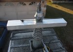
If you will be operating portable, consider the tripod or mount you will use. Ease of setup, size when folded for transport and resistance to shaking in the wind will all matter. If you can create an attachment method that lets you install the antenna on the mount without putting together lots of small parts, setup, takedown and transport will all be easier and less parts will get lost along the way.
Wind loading must be considered. A flat panel antenna mounts close to the boom and isn't too much of a sail. A wire mesh reflector or solid dish mounts further away, sags more and catches more wind. Watch for deflection of your mount as you release the weight of the antenna. If it sags very much, the wind is also likely to move it around. Counterweights help a lot if deflection is a problem. You can limit some of the moving around with bungee cords or pre-stress wires/strings. Remember, the higher the gain on the antenna, the more critical the pointing accuracy and stability becomes. |
|
|
Written by David Rivenburg, AD5OO
|
|
Tuesday, 23 February 2010 17:51 |
|
Measurements of several coax jumpers
We have been concerned about the loss in connecting antennas to routers and A/P units. Various cables, adapters and jumpers are available and no one seems to be making claims about signal loss as they are used.
These measurements were done using a frequency counter, signal generator and microwave power meter. Signals are generated by a Polorad 1105 microwave signal generator. This unit covers 800-2400mhz and delivers a maximum of 0 dbm of output. This represents 1.0mw at 50 ohms. An EIP 535 microwave frequency counter measured the test frequency which was always held to 2400mhz. This is the upper limit of the signal source so it is not possible to test at mid-band. Power was measured by an HP-437B with an 8484A sensor head and required attenuators. The range on this head is 0.3 nanowatts to 10 microwatts so it is impossible to use directly.
The procedure is to warm up all equipment for an hour. Next, these steps are used:
- Set reference power on the generator output dial to 0dbm
- Adjust output frequency to 2400mhz via the frequency counter
- Measure the output power at the signal generator using attenuators
- This includes back to back adapters for coax connectors to be tested
- Make minor adjustments to frequency or power attenuator to get it steady
- Turn on "Relative" display on the power meter (sets display to 0.00 db)
- Remove the sensor head from the generator and insert cable to be tested
- Record direct loss reading (example: -4.09db)
- Gently flex and move cable especially near ends to watch for dropouts
- Remove cable and replace sensor head with adapters on source
- Verify reading is very near 0.00 relative reading set before
- Connect frequency counter and verify near 2400mhz
Testing done in this way is a direct reading of loss in db at the frequency of use and includes the coax connectors and adapters. Adapters can be lossy if poorly made. Below are our findings.
Cable Measurements | Total Loss | Unit Loss
| | 50' Andrew 1/4" Heliax-Superflex with N connectors | 4.87 dB | 0.10 dB/ft
| | 15' length of RG8 style with N connectors | 5.95 dB | 0.40 dB/ft
| | Hawking HAC7SS 7' HPP-100 R-SMA extension cable | 3.43 dB | 0.49 dB/ft
| | Linksys AS2TNC 6' R-TNC antenna stand | 3.45 dB | 0.57 dB/ft |
Adapter Measurements | Total Loss
| Pan Pacific RFA-8892P RJ-SMA/RP-TNC
Pan Pacific RFA-8893P RP-SMA/RJ-TNC | 0.45 dB/pair |
Connector notes:
- Brass SMA connectors require 4-5 in/lb torque to provide the design impedance
|
|
Written by David Rivenburg, AD5OO
|
|
Tuesday, 23 February 2010 17:48 |
What are they? Fiber links are optical ethernet (100base-FX) connections that port to/from CAT5 ethernet (100base-TX/RJ45) connections. Recently, a number of the D-Link DFE-855 transducers became available used. D-Link list price is just under $180 (two required to work). Here is the blurb:
The D-Link DFE-855 is a Fast Ethernet media converter that translates transmission signals from a twisted-pair 100BASE-TX cable to 100BASE-FX fiber optic cable. It expands network data transmission distances beyond the 100 meter limitation of copper wire to a maximum of two kilometers by using fiber optic cable in full duplex.
The DFE-855 provides auto-sensing detection of full duplex or half duplex signaling. It has easy-to-read diagnostic LED´s for continuous status reports on network speed, duplex media access control connection, and network traffic. The DFE-855 uses standard RJ-45 UTP/STP and SC fiber optic connectors and is IEEE 802.3u 100BASE-TX/FX compliant and operates with all devices that adhere to this standard.
These come with a 5vdc, 1.5a brick that uses a standard 120v IEC computer wall cord. They need an SC/SC 62.5/125 dual mode Duplex optical cable set between them. They don't do MDIX so you have to connect one to either the crossover port of a hub, an autosensing switch or use a true crossover cable to connect one directly to a computer. This is because both devices are MDI when one should be either auto-sensing or MDIX. You can join two routers directly since nearly all do autosensing. Testing Testing them is simple. Connect a CAT5 jumper from your router to one transducer/power brick set. Connect your laptop to either a crossover cable or a switch-then to the other device pair. You must connect the TX port of one device to the RX port of the other. Example: Red in TX, Black in RX on the sending end, Black in TX, Red in RX on the receiving end. Open a cmd or shell window and ping your gateway. I was able to leave the router end connected and cycle through all of the other devices w/o relinking the DHCP address. This is because the router "saw" the first optical device and gave it an address during the first test. Between tests, there is no link but the DHCP remained. I ran a dfw.speakeasy.net speed test on the pair and saw exactly the same speed as hard wired to the router. What are they good for? In high RF environments and where there is risk of lightning, ground loops or power surges, optical is the industry standard for separating one network from another. The optical run can also be up to 2km so they are frequently used for long distance links. You can run a CAT5 jumper to a transducer, a number of feet of fiber and another CAT5 jumper on the other end to totally isolate RF and electrical interaction between two lan segments. We are currently investigating alternate (read cheap) sources of fiber that will work with these devices. Weed trimmer stock has been mentioned by some. |
|
|
|
|
|
|
Page 2 of 6 |
|